Unit 4 NYC Rooftop


Spaceship Render
Design 1
Design 2
NYC Rooftops research
 |  |  |
|---|---|---|
 |  |  |
 |  |  |
 |  |  |
I did this research of real rooftops from New York to get an idea of what they look like and what they consist of. I noticed that they have many water towers as well as air conditioning units in the rooftops and windows of the buildings, which I will include in my final project. I also noticed that they vary in shape and are not simply rectangular, which I will take into consideration when designing my own buildings so that they are not simple and are accurate to what they look like in real life. Real images also give me an idea of the lighting and shadows, as they give an accurate representation of how the lighting works with these rooftops and skyscrapers.
Rooftops in games
 |  |  |
|---|---|---|
 |  |  |
 |  |
I researched how rooftops in general look in games to get an idea of how game designers design them to include surfaced used for cover as well as mobility. One of the games I looked at the most was "Mirror's Edge", which is a game that's based around the concept of free running. I focused on this game because it is the most suited for an environment that includes mobility and covering, as in this game you spend most of the time running, jumping and climbing around the level and sometimes there is shooting involved. I also looked at Prototype and Grand Theft Auto IV as they are games based on New York. Prototype involves jumping, climbing and gliding, which gives you a good look at the city's rooftops and makes them more detailed and Grand Theft Auto IV involves flying in helicopters and some rooftop scenes, which shows how they are designed to include cover and takes into consideration player experience. I also looked at an image of Gotham City as one of Batman's methods of transportation includes climbing buildings and moving through rooftops as well as using cover to sneak around. The last game I researched was Max Payne, as it includes scenes where you participate in shootouts in buildings using cover and jumping over obstacles.
NYC Rooftop Development

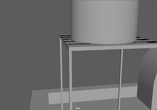
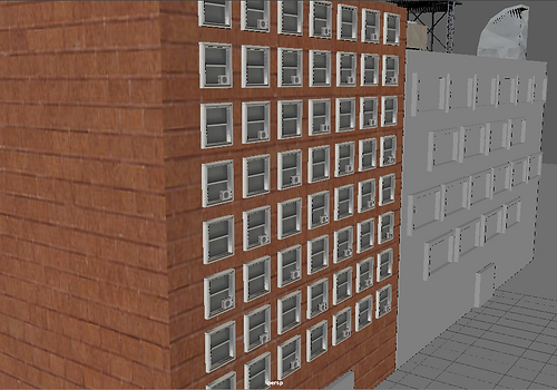
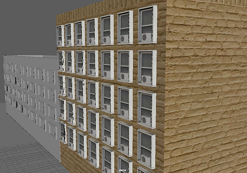
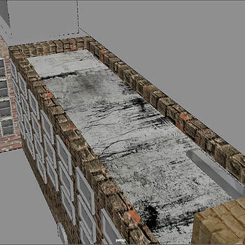
This screenshot shows the state of my NYC inspired building when it was in its initial phase. To create the base building I used the cube polygon tool and adjusted the height, width and depth to make it the size that I wanted it to be. Before adjusting the size I changed the my Maya preferences so that the grid was set to Meters instead of Centimeters, as this will later on be imported into Unity and the size will not be correct if it is set to Centimeters. I made the rooftop through the extrusion tool. Firstly I selected the face at the top to adjust the shape and then extruded towards the inside once more to make the rooftop. I made the windows and air-con units with the cube polygon tool by extruding the face to manipulate the shape and then extruded once again to make the inside, just like I did with the rooftop. To place the cube polygon on the building I made the cube a live surface. I also did this to make the door. I placed the windows multiple times by using the SHIFT + D duplication tool which learns the movement, however they did not align properly.
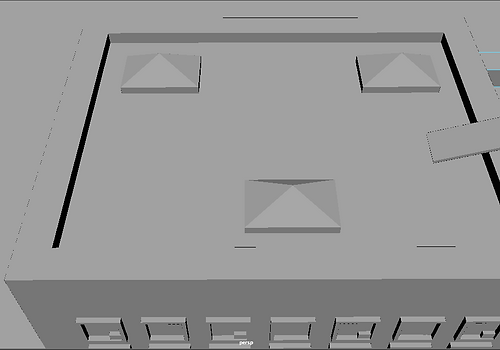
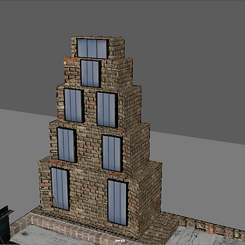
I made this screenshot to show how I made the pyramid shaped window panels on the rooftop. Firstly I used the live surface tool on the building to be able to use the polygon cube tool on it. After this I extruded the top of it upwards and adjusted the shape to make it pyramid shaped. After one was finished, I used SHIFT + D to duplicate it and move its position, and did it once more to place a third one. The placements may be adjusted in the future to a more suitable design.

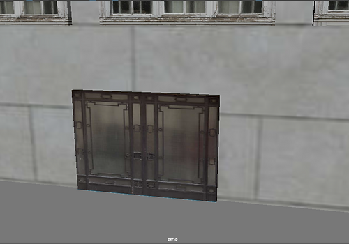
In this image I am showing the second building that I made, as well as its windows and door. I decided to make these windows wider to have a varied design, as well as mixing the arrangement of them to make it more appealing to the eye. These windows were created through the CTRL + E extrusion tool, just like the ones on the other building. The door was also made once again with the live surface tool to use the polygon cube tool on the building which facilitates the creation of the door.

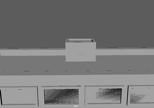
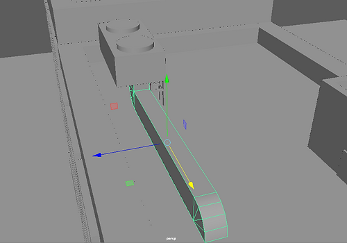
This is a screenshot of the access route to the rooftop from the building. This serves as cover as well as a free running obstacle, which is one of the major reasons that I created this from a game design point of view. I created the base cube by using the live surface tool on the building to use the polygon cube tool on the rooftop, as this made it easier to accurately create it on top of the rooftop with the position and shape that I want it to have. I used the CTRL + E extrusion tool to create the rooftop of it, and used the live surface tool once again on the cube I created to make the door. However I am not too convinced with the positioning of the door and will possibly change it in the future.

I took this screenshot to show that I have fixed the alignment of the windows so that they are now all in a straight line and properly aligned, as before it didn't look correct and it was a visible design error. I had to manually select the window frame as well as the air-con unit by holding shift during selection, as this allows me to select multiple objects at the same time. I then pressed W to enable the translation tool and used the arrows to move them into a position where they are aligned with the window above it as well as the ones next to it.
This images shows the adjustments that I have made to the roof access. I have changed its position by using SHIFT to select the cube and door, and used the translation tool to move it to where I desired. I also changed the positioning of the door as I didn't think it was visually appealing where it was previously positioned.

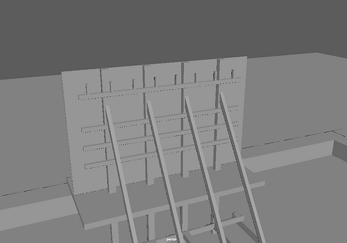
This screenshot was taken to show a ramp that I created for access from one building to the other as well as for free running game play purposes. I created the ramp by using the live surface tool on the building and then creating a slightly elevated cube using the cube polygon tool. To make it into a ramp. I also added some supports underneath it by using this same method, as it would not make sense for it to simply be floating in the air. I created the railings by using the live surface tool on the ramp and then creating them with the polygon cube tool. I had to slightly rotate the railing on the right to align it, and I then used SHIFT + D to duplicate it and I moved it towards the opposite edge, where I needed to rotate it again to align it. I used the rotation tool by pressing E.

I took this screenshot to show how I used the wedge tool to create an air vent. Firstly I used the live surface tool to make a cube on the rooftop. After these I used the CTRL + E extrude tool to to extrude it upwards. After this I right clicked and chose Multi to select the upper face as well as the edge I wanted the wedge to end in. After selecting them I clicked on the square next to the Wedge tool and set the angle to 90 degrees. I then selected the face that was wedged and use CTRL + E to extrude it and make the shape smaller, which would then allow me to wedge it inwards by selecting the correct face and edge on Multi and wedging it at an angle of -90 degrees. Finally, I selected the remaining face and used CTRL + E to extrude it inwards so that it didn't stick out and it looked empty.

This is a screenshot of the supports that I've created for an air-con unit on the rooftop. I initially created the supports by using the live surface tool on the air-con unit and then creating one cube on it that went downwards. I then slightly adjusted its position and shape so that it looked more realistic. after this I had to use SHIFT + D to duplicate it and move it around to make four of them and align them properly. When I finished doing this, I used the live surface tool on one of the supports to create a connection, and then used SHIFT + D to duplicate this connection and moved it towards the supports that were parallel to it . I did this exact same process with the other connection that was left.

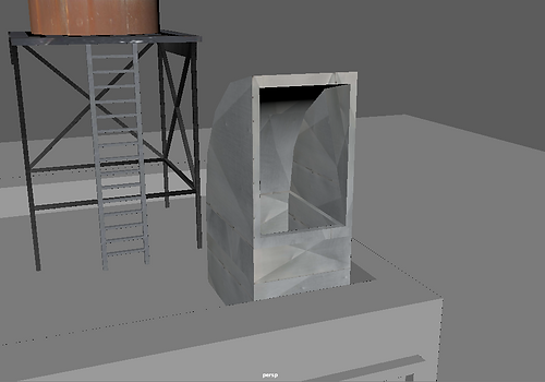
In this screenshot I am showing the air ventilation system that I created. To do this I initially used the live surface tool to create a polygon cube. I then used the wedge tool on each end to wedge it towards the direction that I needed it to, whilst also then wedging it inwards and extruding it to make it seem like there is nothing there. This is meant to be placed underneath the air-con unit, to show how the air travels there. It can also be used as cover or as a free running obstacle.
In this image I am showing the current positioning of the air ventilation system. To fit it underneath it and between where the supports will be placed I had to select it and scale it to make it smaller. To accurately adjust the scale I chose the attribute editor and edited the numbers of the scales. I chose this method because it was more accurate than using the arrows as I could easily adjust the numeric values so that the size changed exactly the amount that I wanted it to.
Bezier Curve Tool


Wedge Tool


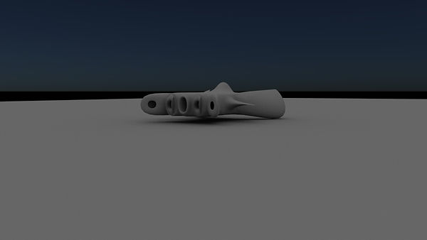
This screenshot shows the design that I made using the Bezier Curve Tool. This tool is used by clicking on points to create vertices which join to each other through straight lines, which can be modified by clicking and dragging to create curves. This tool allowed me to be freely design an object the way I wanted to and was easy to use as well as accurate.
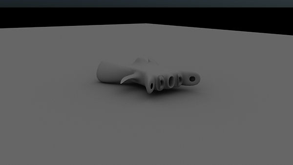
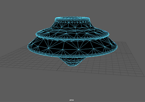
I took this image to show the physical form of the design that I had created using the Bezier Curve Tool. I created this image by selecting the design and using the Revolve tool, which automatically created the physical form as well as the remainder that was not included in the design. I like this function of the Bezier Curve Tool as it is time saving when trying to quickly create/model an object as it is as easy as quickly plotting the design with the vertices of the Bezier Curve Tool and then using the Revolve tool. However, the Revolve tool has to be set to create a polygonal object as otherwise you will not be able to select the faces for the next step.
This final screenshot shows the final product of my Bezier Curve Tool experimentation. The problem that I encountered with the Bezier Curve Tool was that the object is created inside-out when used the Revolve tool, which causes troubles when smoothing and rendering. However, this can easily be solved if you set the Bezier Curve Tool to create a polygonal object, as by selecting the all of the faces of the object you can then use the Reverse tool to make the object appear properly and thus solve the problems that would be caused when trying to smooth or render the object.
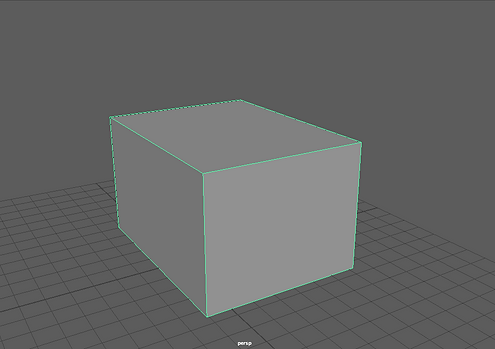
In this screenshot I am showing my first step of my experimentation with the Wedge Tool. In this first step all that I have done is create a cube with the Polygon Cube Tool. The next step right after this was to extrude the upper face upwards to make the cube bigger as I was not happy with the current size and also wanted to create a new polygon.
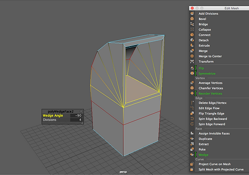
This screenshot was taken to show my initial use of the Wedge Tool, which was to attempt to create an air vent. To do this I right clicked and selected Multi,which allows you to select multiple parts of the shape such as what was required in this case, which was the upper face and the edge I wanted it to wedge towards. Once I selected this I used the wedge tool which is shown on-screen and set it to 90 degrees so that it would wedge the way I wanted it to.
This screenshot shows the next step of the process, which involved using the Extrude tool to extrude the face and make it smaller. I did this so that the air vent would have a frame. After this I right clicked to select Multi once more and then selected by using SHIFT + click to select the face and edge that I wanted to wedge. This time I wanted the wedge to be inwards so that an opening would be created, therefore I changed the angle to -90 which successfully wedged the face inwards.
This is my final screenshot showing the final process as well as the end result of the air vent that I attempted to create. After using the wedge tool I had to extrude the face once more to make it smaller and then extruding once more but this time dragging it downwards to create an opening. The first extrusion was done to create an inner frame that would make it more visually appealing and realistic.
Bridge Tool

This screenshot shows the starting process of my experimentation with the Bridge Tool. To start off I created a square block using the polygon cube tool and dragging on the grid to create a suitable size for this experimentation.

This is a screenshot of the next step that I made. This shows the modifications that I have done to the original block. To do this I right clicked to choose the face tool and then chose the face at the bottom and extruded it using Ctrl + E. After this I dragged it outwards to make a bigger base for the shape that I am going to create. After I finished creating the base I then chose the upper face and extruded upwards to create a block opposite the original one that I had created. I made it higher than the original so that the connection goes upwards.
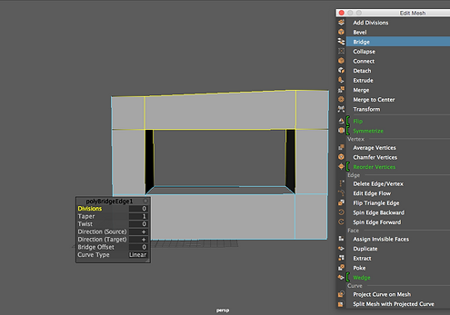
This image shows the final process of my bridge tool experimentation. To do this I selected the two faces that I wanted to connect by holding SHIFT to select both of them. After doing this I clicked on the bridge tool that is shown on the image too, which proceeded to create a connection between both of the faces that I selected. This tool is useless as it quickly creates a connection between two faces, which can be used to create many things such as windows. However, the downside of this tool is that it can't be between two different objects, therefore you will have to either create a single block and extrude it to make what you want or combine the meshes into one single object.

This screenshot shows some modifications that I made to the support for the air-con unit. I added two extra supports because I noticed that they were missing after looking at my reference images. To add these I used the live object tool on one of the supports as this allows me to place them directly onto the object, which is more accurate than doing it on the grid and then moving it and scaling it so that it fits. After this I duplicated them and moved & rotated them so that they would fit in on the rest of the sides that were left.
I took this screenshot to show how I made the rest of supports. To make this I selected all of the objects that made the first support and merged them into one object. I then used CTRL + D to duplicate it and then proceed to position them into where they belong. I had to do this process three times as there were 3 corners without the support.

I included this screenshot to show the modifications that I made to one of the supports, as it was incorrectly aligned and therefore required adjustments as it didn't look right. To do this I re-positioned the camera into an angle that allowed me to directly compare the support to one of the others. I then took advantage of this comparison angle to accurately position the support in line with the others.
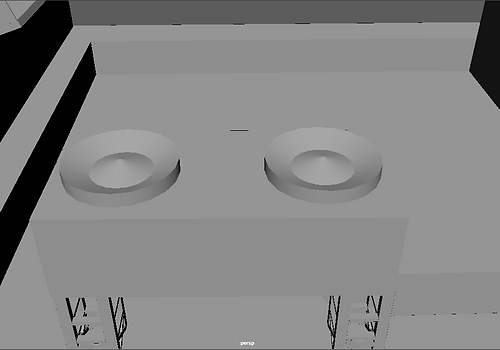
This image shows some modifications that I made to the fans of the air-con unit. I made them look more realistic by extruding the upper face and then adjusting the arrows until it reached this shape. I noticed that they looked too simple and unrealistic after taking a second look at my reference image, and then decided to modify this to achieve the correct shape.

This is a screenshot of my first attempt at texturing. I didn't know how to use actual textures at the time so I simply changed the colours. To do this I simply chose the object, held right click and went to "Assign new material". I chose Lambert, which is the default material for Maya, and proceeded to click on the colour option and choose one that looked similar to what I was trying to make. In this case the object is supposed to be a wooden ramp, therefore I chose a brownish colour that resembled wood.
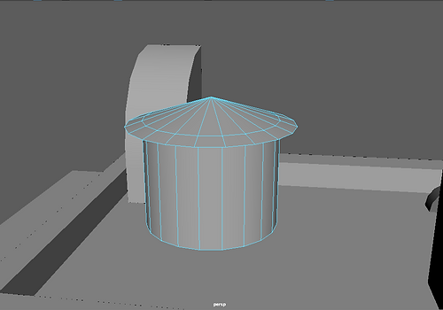
This image shows the water tower that I made. To make this I used the live object tool to make it on the rooftop. I then selected all of the faces on the top of it and used CTRL + E to extrude them. I extruded them slightly upwards and outwards to create the upper part of the water tower. I adjusted this accurately to recreate the water towers that appear in my reference images.

This screenshot shows the base that I made for the water tower.To create this I use the live object tool on the water tower and then used the polygon cube tool to create the base on it. I then adjusted it so that the water tower fits on it, and then created some more divisions on it. To make it seems like there are gaps I made some of the divisions transparent. I made it seem like this because many of the water towers on my reference images have bases which are divided into multiple boards.
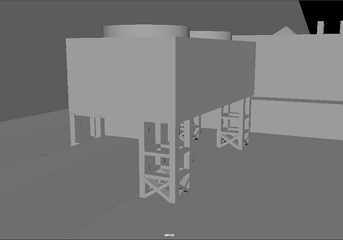
In this image I am showing how I created the initial supports for the water tower. I used the live object tool on the base and then used the polygon cube tool to create the supports more accurately. I used the attribute editor to accurately adjust the positioning and scale of the supports. After creating one of them I used CTRL + D to duplicate it and I then moved it into the position I wanted it to. I had to repeat this process a few times to create all of the supports.

I took this screenshot to show a more advanced state of the water tower. The new addition is the extra support that was added based on various reference images. I did this by duplicating one of the supports that was already made and then positioning, scaling and rotating it so that it would fit. I then duplicated this new support that was created and I re-positioned and re-scaled it so that it would also fit and was aligned with the support that it was crossing with.

This is a border that I made for the water tower. When looking at reference images I noticed that they had borders on the sides, however mine did not and therefore I decided to create these. To do it I used the live object tool to then use the polygon cube tool and accurately create it in the position that I wanted it to be in, as well as with an accurate scale that I then modified through the attribute editor to make it more accurately sized while looking at various reference images that indicated what it should look like.
This screenshot shows the finished supports of the water tower that I created. To easily place them on the required sides I used CTRL + D to duplicate one and then place on the side that I wanted to, and then did it once more to place the remaining one. This process was slightly difficult as I had to modify the rotation of them individually to get the correct placement, which made the process a lot longer and more complicated as getting all of the angles and placements was really important so that they didn't look out of place and would fit in correctly. I also had to change the positioning of one of them as it was covering up the side that faces the outside, which is where the ladder was meant to go.

This screenshot shows my first attempt at texturing. Before I started texturing I first acquired the texture that I wanted to apply and put it inside the scene folder where it is supposed to be in. After doing these preparations I selected the faces that I wanted to apply the texture to and I right-clicked and selected "Assign new material..." and then chose "Lambert". After this I clicked on the checkered box that appears next to the colour and chose the option "File". After this, a new option appeared which allowed me to choose the texture's file. To choose it I had to click on the folder that appeared next to this option and then selected said texture. At first it wasn't applied properly, so I went to "UV" and chose planar (with its settings adjusted so that it fits the best plane). I did this to each window individually, and adjusted them until they looked right.
 |  |
|---|

I took this screenshot to show how I textured the door of the rooftop entrance. To do this I selected the front face and assigned Lambert as a new material. I then clicked on the checkered box next to colour to change what's used to file, and selected the file of the door. I then clicked UV and then planar to adjust the texture onto the door and modified it so that it looked the way it was meant to look. For the frame of the door I used the face selection to select them individually and applied a new material to them. This time, instead of adding a new texture, I modified the colour so that it blended in with the front of the door.

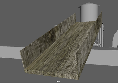
This images shows the first part of my ramp texturing process. For this part I only textured the planks of the ramp and left the railings untextured but with the brown colour that I had put in them before. Texturing this was more difficult, as I had to individually adjust each face using planar followed by modifying the values so that it all looked right and like it joined up together which made it blend in. In various attempts one of the faces kept looking out of place, so it took me various tries until I got the ramp to look the way I wanted it to.
This shows my fully textured ramp. To texture the railings I had to modify the current material and click on the checkered box to select the file option. This time I adjusted the texture by going into UV and then Automatic so that it automatically adjusted it, which gave a satisfactory result. However, I still had to modify it so that it didn't look out of place and it blended in with the planks of the ramp.
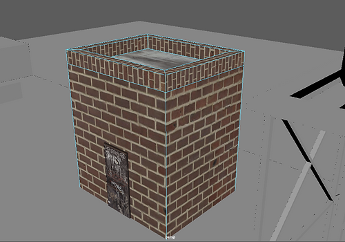
This screenshot shows the texturing of my rooftop entrance. I got the brick texture from an external website and then applied it to the building by using the previous said method. When modifying the positioning of the textures I had to individually use Planar on each face so that it turned out correctly, including the upper ledges so that it looked more realistic and had a different design using the same base texture. I modified the texture on one ledge and then used copy and paste to modify the other ledges' projection length and width as well as rotation so that it would be identical to the others.

I took this screenshot to show how I modelled my water tower. I used a rusted metal texture that I found externally through a texture website and applied it to the water tower. this was easy to texture as by using planar on all of the faces together created a good and realistic pattern. However, I used a different rsuted metal texture for the roof of it and the roof was harder to texture due to the divisions. I had to texture each side at a time so that it looked parallel and to add realism. This image also shows the gaps that are in the base of the water tower, which I created by selecting those specific faces and adjusting their material so that they were transparent instead of deleting them.

This image shows my textured water tower base and support as well as the ladder. To texture the water based I searched up a black rusted metal textured, as that was the colour of it in the images that I used as reference, and then textured it. For the rest of the supports I had to individually texture each one of them so that the texture would be applied to them properly, as if I did it to all of them at once the texture would come out blurry and would have repetitive patterns all around. I also had to individually modify the projection of each of the ladder steps as well as the ladder supports, as otherwise the same problem would've occurred.

This screenshot shows how I textured the air vent conduct. To texture it I searched for a texture that was an image of a side of an air conduct and then I assigned a new material to which I applied the texture. After this I adjusted the texture through planar so that it looked realistic. I adjusted it while looking at a reference image of an air conduct in a realistic game as well as an actual photograph of an air conduct in New York. For this object I had to texture it face by face as otherwise it didn't look realistic and some parts would've looked blurry. I also had to adjust it so that the lines crossed over and therefore looked like it was part of the same object instead of something that was made differently.

I took this screenshot to show how I modelled the air con unit as well as to show it textured alongside the air conduct. This texture does not seem too convincing to me, therefore I will possibly change it in the future to one which has a grey tone so that it blends in with the metallic colour of the air conduct. I also textured the supports of the air con unit with a metallic texture that would seem realistic based on various images that I used as reference which were actualy photographs from New York as well as game representations of it which allowed me to check how they were designed and placed to fit in as cover for game design purposes as it can be a big part of the game's mechanics.
This image shows an air vent that I have created. I did not show the whole process as I have explained how one is created previously. I used the same texture as the air con conduct so that it looks realistic as well as being directly related to it through the colour and texture scheme of it. The texture was difficult to adjust as it had to be textured inside as well, unlike the other objects where they were only textured on the outside. I had to use planar individually on each face so that the textures didn't look bad and so that they matched each other.
This is a screenshot of my first building textured alongside the windows and air con units. The building was easy to texture but will probably be re-textured in the future as I think that the bricks may look too big and out of proportion. The way in which I textured the windows was by using planar on one of them, adjusting the texture so that it fitted the window correctly and I then used SHIFT + D to duplicate it and replaced the non-textured windows with the textured one. I did this same process with the air con units.
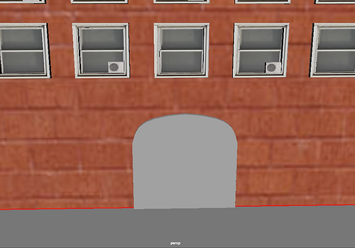
This is the door of my first building. I manipulated the squared shape of it into an arched door by using extrusions. This was slightly difficult to do for me as sometimes while I was extruding the faces would not join up. To fix this I had to change the way I was extruding as well as which faces I was extruding, as I found that the main problem was the order in which I was extruding the faces.
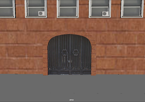
This is a more developed and textured version of the door shown above. I further extruded the arched shape of the door to make it more arched. I used the same textured that I used on the building for the arched section so that it blended in and I used a double door texture that would suit the door based on some of my reference images that I used to model the door. Texturing the door's arch was difficult as I had to individually texture and adjust each side so that it didn't look uneven.
This was my first attempt at texturing my second building. However I was not happy with this result as the bricks are too big and look out of proportion. However I decided to include this in my website to show some of the textures that I decided to try out. I also textured the roof, which I did not change as I liked how it looked and I thought I textured it well and accurately.

These are my textured windows for my second building. I had to slightly modify their size to find a fitting texture as I had made them out of proportion. Texturing the first window was easy as it is a simple shape. To texture the rest I used SHIFT + D to duplicate the first window and replaced the rest of the windows with it as it was a faster and easier process. However this required a lot of accuracy and therefore I had to note down their position on each axis to accurately move the duplicated window.
This is my textured window for my second building. For this door I decided to keep it simple and didn't make it arched or gave it an advanced shape like the previous door. I searched for a double door metallic texture that would fit in with the building and would be similar to the previous door as well without being the same to add some variety to the textures. This was easy to texture as all I had to modify was the front face, which I textured using planar. I used a new material for the top and sides and changed the colour to a shade of black that would be similar to the main texture.

This is my re-texture of my second building. I chose a different seamless brick texture that had smaller bricks and applied it individually to each one of the faces so that it seemed even and they joined each other. I textured the edges differently so that the difference between the edge and the normal wall was noticeable, as well as basing this off some of the buildings that I have seen in some of my reference images. This was slightly difficult to texture for me as it was hard to get the faces' textures to align properly with each other.

This is my second water tower which I included in the rooftop of a different building. To place it there I used CTRL + D to duplicate it and then I used the translation tool to move it to the building that I wanted to. Once I moved it I applied a new texture to it by creating a new material so that it wasn't exactly the same as the previous one that I had modeled to include some variety in the designs. I also changed the texture of the water tower's roof so that it was even more different, as well as making the base be fully solid with no transparency to show that in NYC all of the water towers were not exactly the same when it came to their design.

This screenshot shows the texture of my third building. I chose a different coloured texture to add some variety to the brick layout throughout the buildings. However, I used the same texture for the rooftop as for the first building as this is a texture that fits well with this setting and blends in with the buildings. Texturing the building gave me some problems with the alignment as the two faces on the sides were a different width than the back and front, which meant that I could not use the same measurements and therefore had to be adjusted differently.
These are my textured windows for my third building. To texture them correctly I had to modify their shape as I had initially modeled them incorrectly and the texture did not fit in correctly in the window. For these windows I decided to include an air con unit situated in the middle of each window to show that in some buildings everyone has one, while in other buildings such as the first one only some people have an air con unit. For the air con unit I simply duplicated the one that I had previously modeled and textured and simply re-scaled it so that its size was right for these windows.
 |
|---|
 |
This gallery shows how I textured the fans of the air con located on the top of my first building's rooftop. I searched for a texture of the fans of an air con and then used it to texture these ones. I used planar and it was easy to texture as it is a simple shape. I individually textured both and had to rotate it as when I first applied planar the texture was implemented the wrong way round.

This screenshot shows some of the new buildings that I created for this scene. I decided to make them quite big based on the reference images that I was using as while looking at them I noticed that the size in buildings varied quite a bit. In one of the new buildings I left an open space so that you could drop down from it onto another building or could jump onto it from the one on a lower level.

This shows my textured windows for one of my new buildings, as well as some of the windows for another one of my buildings one the side. For these windows I simply duplicated one that I previously modeled and textured and then calculated the distance that should be between each one. After this I used the SHIFT + D duplication method that repeats your movement to place them in those places. I repeated this for each row.

This is a building that I created through experimentation while extruding. I think that the design seems unique and is slightly similar to some of the layered buildings that I have seen in some of my reference images, therefore it is a building design that I might keep and use in my final model. I made this by slightly extruding inwards each time and then extruding upwards, which made the slightly indented shape that can be seen in the image. The first time I extruded I liked the shape that I had made, and then repeatedly made it whilst making each floor slightly smaller than the previous one until I thought it had enough floors.

This was my initial step towards making a rooftop billboard based on a reference image that I had found. This image shows the basic supports of the base laid out which I created by making the building a live surface and then creating them using the polygon cube tool. When I made them I adjusted the width, depth and height until it looked correct when compared to the reference image. When this was achieved I duplicated it and placed it elsewhere multiple times. I also had to put a support that went from one end to the other, and I had to do this with high precision and accuracy so that it fit in perfectly with each end.

This was the next step that I took whilst modelling my rooftop billboard. In this image I duplicated the support that went from end to end and place it on the opposite side. I also created some new supports that went between the supports that go from end to end. The reference image had four of these, so I had to duplicated it a few times. After creating these supports I decided to start creating the base on which the billboard itself will be placed on, although it is only a rough placement and size in this image and not accurate.

In this screenshot I have correctly placed the base as well started creating the billboard. I had to increase the height of the initial four supports so that it was at the height of the billboard. I based the height of the billboard on the reference image that I used. However, the sizes of this billboard are not final and will probably need to be increased.

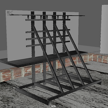
Here I am showing that I have added some new supports that join the initial supports to the billboard, which would help it stand in its place. This was slightly tricky to do as I had to carefully rotate and scale them so that they would fit in perfectly with the supports in the floor as well as with the billboard's support.

In this screenshot you can see the new supports that I added to the back of the billboard. I implemented this based on some reference images as well as because it would be needed to give the billboard some extra support. This was easy to do as all I did was use the live surface tool on one of the upwards supports and created a polygon cube on it. After this I resized it so that it was the correct size and then duplicated it upwards twice with the required distance that would make it end right under the diagonal supports.
I am showing some new supports that I have created. I have implemented one new horizontal support on the billboard as well as some vertical ones on top of this one. These vertical ones were implemented because the billboard's platform will be placed on top of these. They were slightly difficult to position as I had to use trial and error until I found the correct measurements to make it evenly placed.


These screenshots show the platform that I have implemented into my billboard. This is where people would go to modify the upper part of the billboard. It was easy to place as I made it with the live surface tool. The second screenshot also shows how I have resized the billboard and the base of it as well as the platform itself as when I looked at my reference image I realised that the size was not correct.

In this image I am showing the texture for one of my new buildings. I like the texture as I think it is really clean, however I will need to resize it as well as the edges as it seems to be too big and out of scale which makes it look unnatural and out of proportion. This time it was easy to texture however due to the experience that I have gained while texturing the other buildings.
This is the rooftop of the building above. I decided to show a close-up so that the texture is more noticeable. It was extremely easy to texture, as when I used Planar it instantly adjusted into a good position, all that I had to adjust was the width and height a bit so that it looked more realistic.

This is one of my new buildings. I decided to use textures from a different website this time which resulted in cleaner and smoother results. When texturing this building I took into consideration the size of the bricks as well as making sure that the textures join through the edges. You can also see the texture of the rooftop, which was easy to adjust.

These two images show the texturing of one of my final buildings. The brick texturing was slightly hard to adjust in this one due to the texture's size as the bricks were slightly oversized. For the windows, I used a texture for the inside glass and then used a new material for the frame and made it a light colour that was similar to the one that appears on the texture.
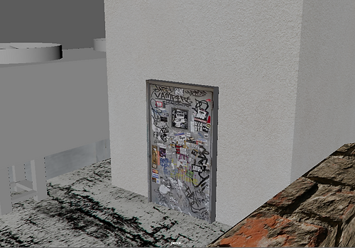
This is the texture for my second rooftop entrance. I chose a different coloured door that still had some graffiti on to match the urban theme that I was aiming for. For the entrance building itself I decided to go for a clean, white texture that was not made out of bricks to add some variety that can be found throughout the city of New York as well as throughout many of the best-selling games out there.


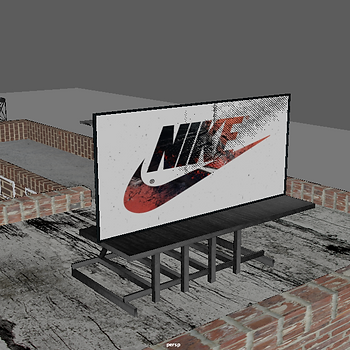
With these screenshots I am showing the texturing process of my billboard. Initially, to texture the supports and base of my billboard I re-used one of my previous metal textures that was dark to make it similar to my reference images. This was a really lengthy as I had to individually texture every support face by face. However, with the supports that had multiple copies I simply textured one of them and duplicated it onto the position of the others. To texture the metallic parts of my billboard I searched for a high quality metallic texture that was different yet similar to the others. I extruded some parts of the front so that the billboard had a frame, which made it easier to texture it while leaving the face in which the advertisement would go in free. I had to individually texture the frame as if I tried to adjust the texture of the frame all at once it would come out blurry and would not look good. I searched for an advertisement that would be related to what the game would be. In this case, I chose Nike as it is a brand that creates sports shoes, which in my opinion is suitable as this would be a free-running game.


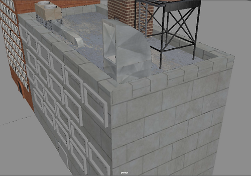
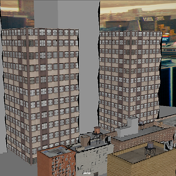
This is my texturing of my experimental skyscraper. This was really difficult and lengthy to texture as it had a lot of faces that had to be textured individually so that they were even and didn't look out of proportion. I used planar throughout this process and for many of the faces I used the same proportions as I found that it fitted well by doing so. When modelling the windows I look at many reference images and try to create something similar yet original that would have my own unique touch, as this was the purpose of creating this building as well. To texture it I used the same texture as for the rooftop skylights that I included in my first building as well as creating extrusions to make some window frames and then making these dark, as seen in the texture.

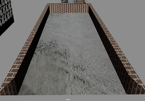
I textured this road to add some realism to the ground level. To texture this I used the "Insert Edge Loop" tool to make some specific divisions where I wanted the road to go. After this I selected the face that I had just created and created a new material on it in which I used the road texture that I had found.

This is the second air con that I have duplicated onto one of my new buildings. I used a different texture than the one used on the original copy to add some variation. I also changed it because I thought that it looked better and was more accurate to reality. This was easy to texture as the shape of the air con unit is really simple. However, I had to resize the air con as well as the vent because I wanted to make it usable as something you can climb onto. I wanted this so that you could then climb onto the rooftop entrance and after that onto the next building, adding some parkour/free-running elements that tie into game design.

This shows how I modeled the front of a crate, which I then duplicated onto each side. It was slightly tricky to align the diagonal part as if it was too long it would stick out onto each side or through the bottom and top parts. For the bottom and top what I did was create one of them using a reference image of a crate to adjust the size of it and then duplicated it onto the opposite section of the front to make it even.

This is the final model for my crates. As stated previously I duplicated the front side's supports onto each side as well as the top. Modelling was quite tricky as I had to use a wood texture instead of a crate texture because I was unable of adjusting it properly. I had to adjust every side of each support, which became quite tedious. However, I only textured one crate and duplicated it onto the position of the other two crates to make the process easier and faster.

This is a screenshot of the rooftop entrance of one of the buildings. This shows the initial modelling of it and what the basic shape of it is. I made this by making a cube with the polygon cube tool and then I extruded one of the sides to make it wider. I also did this because I could then extrude the top of this side without affecting the other one. After the side was extruded I extruded the top to make it taller and then extruded once more to make a small ledge. I used this same process on the other side to make another ledge.
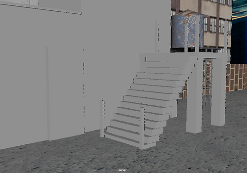
In this image I am showing the staircase that I have made to access the second floor of the rooftop entrance as well as the base and basic supports of it. To make the stairs I created one step and then used Shift + D to repeatedly duplicate the movement that I did which would allow me to create this with ease. Before this however I created the base and the four main supports that go with it as well as the supports on top. The ones that are beside the final step were made after creating the steps as I did not fully know where the steps would end.

This is my finished staircase. I have added railings and extra supports that were necessary for realism based on my reference image. For the diagonal railings I had to accurately figure out the right angle that had to be used. After this I used the SHIFT + D duplication method to duplicate the movement of the supports so that it would be completed easily. To create the connection between two railings that are on top of the base I extruded the supports upwards a bit and then extruded them in that direction. I chose this method instead of making a new cube because I found it to be a more accurate and comfortable method.

This shows my initial texturing for the staircase. I chose a metallic texture as I thought it would be suitable in my environment. However, the steps will consist of two different textures. One of these textures will be the one used on the rest of the staircase and the other will be a dark black metallic texture that will make the steps stand out and be more noticeable. Texturing the staircase was slightly time consuming as I had to individually texture each face of the railings as they were shaped differently and therefore could not be duplicated. However I duplicated the supports of the railings so that it would be an easier and faster process.
The Third and the Seventh (Architectural Visualization)

The Third and the Seventh is an architectural visualisation made by Alex Roman. It was made through 3D modelling software. It began with the idea of compiling a number of loose pieces that he had created and then adding more material with a less structured timeline that would add mystery to the slow and eventual reveal of what was modelled. Alex Roman used the photographer and the cameras as narrative devices for the story, as the positioning and angle of each shot added some logical sense into the story as the film progressed, as you would slowly connect each of the shots and this would slowly reveal a much larger picture and story than what was individually told in each of these shots on their own and thus giving them sense.
What draws my attention the most from this architectural visualisation is Alex Roman's use of lighting in his shots as well as the depth of field, as I feel like when he goes out of focus at the start of the shot and then slowly goes back into focus adds a sense of mystery and reveal to that shot which makes it more interesting than a regular shot would. I also like that there's no transition between each shot, as it makes it look random when in reality it is structured to slowly reveal the building without anybody noticing, which in my opinion is a genius thing to do.
Ras-Al Khaimah (Architectural Render)

I was unable to find another architectural visualization to research so I instead chose this architectural render. This is a render of Ras-Al Khaimah made by MIR Visuals through 3D modelling software. I chose this one because the form of the building seems really interesting, as well as the angle that was used which shows how important it is as well as its size. In other images it is show that it is located on the seaside, and that it has some swimming pools. I used this as research because I would like to be able to model to this level in the future, as I find this to be very impressive. I was also impressed with how the lighting was used to make the more important parts of this render stand out more, as this lighting makes you focus more on the main building instead of the trees and green that is below it.
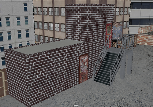
In this screenshot I am showing the end result of texturing my final rooftop entrance. Texturing the steps of the stairs was a slightly complicated yet simple process, as adjusting the textures was simple but I had to re-texture the outside face as it as like this on the research image that I was using, which provided realism to this. To texture the buildings I used a different texture that was not used before to add some variety, and used the same measurements for each face so that they were equal and looked correct. I used a different texture for each door and made sure they both included graffiti so that it had the urban environment that many New York neighbourhoods have.


These are the extra skyscrapers that I textured to make the environment more similar to what New York looks like in real life, with different sized buildings that widely vary as well as a mix of urban, office and modern structures. To model these, I made one initial cube, textured it to look like a building and then duplicated it multiple times. To position these buildings I used the top view provided by Maya, which allows me to accurately place and align the buildings in a manner that seemed accurate and realistic for me.
Final renders


Project evaluation
The project theme was to model a small portion of a city based on New York City as well as games that are also based on it. I enjoyed this theme as I am a fan of many games based on cities like this one, such as Grand Theft Auto IV and Mirror's Edge. I also enjoyed this as I looked forward to modelling an environment.
The most enjoyable part of the project for me was trying to model various buildings, doors and such while looking at a reference image and trying to make it as lifelike as possible. I really enjoyed this because of the satisfaction than I felt when looking back on the final product and thinking that it is incredibly similar.
I have learned a lot of new techniques as I am new to this type of 3D modelling. The techniques that I have learned were extrusion, bezier curve tool, bridge tool, texturing, lighting and the wedge tool.
I really enjoyed learning about the Bezier Curve Tool as I think that it is really fun to model something with it. However, my favourite technique that I would like to further develop has to be extruding as this allowed me to easily create many buildings, crates, air cons and various more objects that are located around my rooftops with precision and accuracy to how it is in reality.
During this project I researched the level design aspect of games. The games that I focused my research around were Mirror's Edge, Mirror's Edge: Catalyst, the Grand Theft Auto series and Prototype as their cities were similar to New York. They greatly influence my project as I made my water towers to look like the ones in Grand Theft Auto. However, my biggest influence was Mirror's Edge as I based my air con and air vent system around it as well as the layout of my buildings, as it was a great environment for a free-running game.
In my opinion the most successful part of the project would be the models that I have made, as I feel like the models are well textured and are rich in detail, which can be seen in the final renders.
I encountered many problems with texturing throughout my project as I saw that some of my textures looked unrealistic a while after texturing them. I learned from this as from the moment that I realised that some textured didn't look quite right I started modifying most of my textures to make them repeated, which would make them look smaller. However this could only be done with seamless textures, so I made sure that the textures that I used were like this.
If I was given the chance to complete the project again I would try to add even more models, such as more highly detailed buildings, a crane that would allow transport from one side to the other through a direct route that passes through the middle and many more. I would also do my texturing properly from the start to save some time.