Unit 10:Characteristics and contexts in art & design
Experimentation
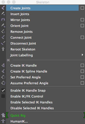
Auto-Rig

Importing


Manual Rigging


Arm Experimentation + Hand Rigging


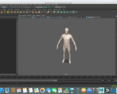
To experiment with rigging on Maya I went on Mudbox and imported a human body model from the program. I selected it by using right click and clicking on select. I then went to file and used "Send to Maya > Update Current Scene" to make the human model appear on Maya.
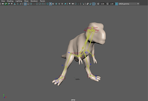
My first experimentation was auto-rigging. I selected the human model that I imported from Mudbox and opened the Quick Rig menu. After this I clicked on Auto-Rig so that it would be automatically rigged. These screenshots show the final result as well as some experimentation that I did moving the joints around. I also showed the section that allows you to quickly select different joints instead of having to manually click on them. I also tried the auto-rig on a T-Rex model that I also imported from Mudbox. However, it didn't rig it well and some joints did not work properly.
Here I decided to try some manual rigging for which I used the "create joint" tool. I adjusted some layers and vies to make the reptile that I imported from Mudbox be transparent and then switched to the side view to get a good view of one half of its body as I planned on mirroring the leg joints onto the other side when finished. The first joint was the spine joint which I placed accordingly. After this, I had to press G every time I finished with a section to choose a different joint from which I would create other joints.
After I finished creating the joints I went back to the main view and noticed that the leg joints weren't on the legs, therefore I had to move them into place manually.
Once I moved the joints into place I selected the joints and used the mirror joints tool to mirror them onto the other side. I had to change the mirror across section to YZ so that it would be mirrored properly.

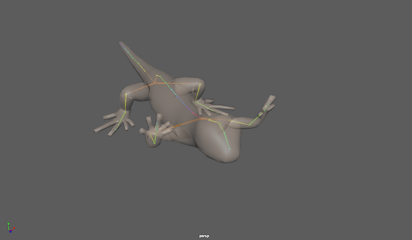

After the joints were mirrored and put in place I then had to put them into the skin, which I did by selecting both the joints and the model and then using the "Bind Skin" tool. I also included some experimentation that I did with the joints to test and check if they were working properly by rotating them to see if the model would move accordingly.
As I successfully rigged the reptile I decided to import an arm from the Maya content browser to rig it and do some experimentation and testing with the arm as well as develop my rigging skills.
This is the finished arm fully rigged and with the joints binded to the skin.
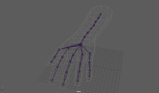
Whilst doing the auto-rig on the human body I noticed that it didn't rig the hands and fingers, therefore I decided to manually rig another body including the fingers and hands of it. This screenshot shows the body with the joints binded to the skin.
Mech Research
Mech Idea

 |  |  |
|---|---|---|
 |  |  |
 |  |
I based my research around mechs from Zone of the Enders and Gundam as I want to use these as reference because of their style, since these are the types of mechs that I personally like the most. I think that they may be more complicated to model than conventional mechs as they have a lot of small details and complex shapes within the designs.
My main idea is to model a mech that is similar to those of Zone of the Enders. I will keep it more simple than the ones in the game and first and may develop on it depending on the time that I will have remaining.
Development


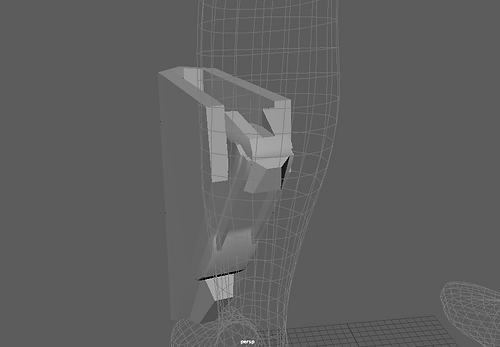
This was the initial step towards modelling the leg of the mech. I created a cube, adjusted its dimensions and then extruded to make the shape that I wanted.
After extruding and getting my desired shape I mirrored it and made sure that the edges were joined together to create the base of the leg of the mech.
Once the base was done I started working on the details at the back. For this part I simply used a cube and resized it as well as repositioned the vertices to adjust it accordingly to what I wanted it to look like.
After creating this part I extended the detail and added the upper part. This will kept simple initially and will be extended upon with additional details if I have enough time left.


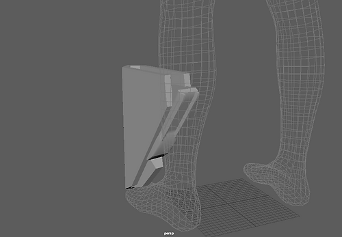


I added additional details by creating cubes and adjusting their rotation and scale so that it fitted what I wanted to create. I tried using the snap tool at first, however I found it easier to just create a cube and adjust everything manually.
Once these details were finished I had to create a cube that would go on the to. To do this I adjusted the scale and rotation f the cube and then selected its vertices and moved them accordingly until I got the shape that I as aiming for.
Here I created another detail. To create this I made a simple cube and used the extrusion tool as well as the rotation tool to create the sides that branch out.
To place this detail on the leg I had to adjust the vertices' position so that it would fit in properly and would get the correct shape at the same time.
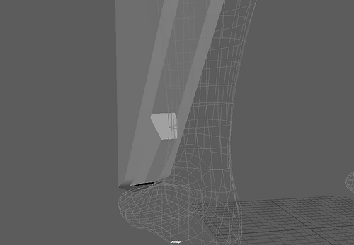
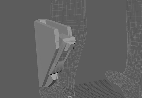
This is the joint that will act as a knee connect this part of the leg to the rest. To create it I started off with a cube and then use the extrude tool to adjust the shape of it as. Many extrusions were required for each layer of the joint and it was time consuming as I got it wrong a few times.
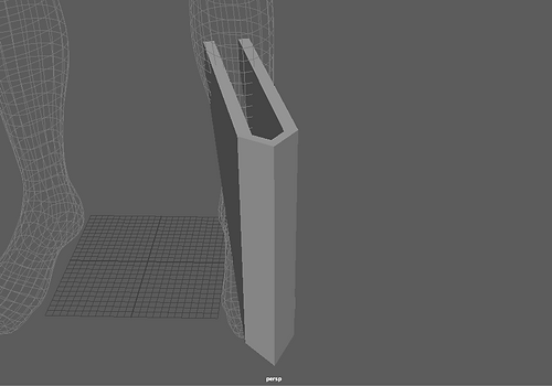
In this screenshot I am showing a knee guard that would be covering the joint. Just like I did with the base of the leg I created a simple use and extruded to create the shape in the direction that i wanted it. I achieved this direction by using the rotation tool and rotating where the face was looking at.
After this I mirrored the side that I created to make it symmetrical as well as to easily create the whole knee guard.
Here is a component that will be the rest of the knee. I made a simple cube and then uses the edge tool to add more vertices and faces to it. Thanks to the addition to these I could manipulate them to create the shape that I was aiming for by moving their positioning.
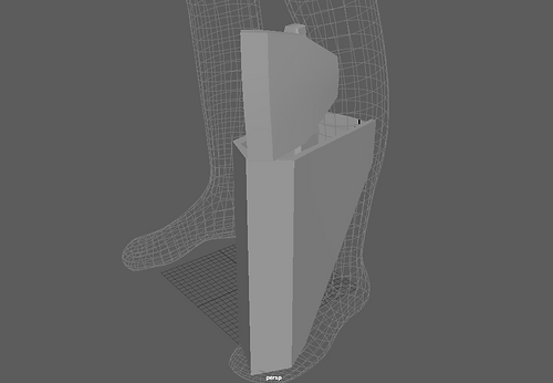
After creating the first part of the leg I create what youd be the inside and main support point of the leg. I simply created a cylinder and adjusted its size and rotation.
Once I finish this part I then went back to the leg and used the extrude tool to finish it off as the back part was missing.
Once I finished the leg I added a sphere which would act as the joint between the whole leg and the main body. Once I created it and adjusted it accordingly so that it would fit I mirrored everything so that it would be the exact same on the other side of my mech.
Once I mirrored the legs I used a cube as a placeholder for the chest and then proceeded t create a type of wristguard for my mech by using a cube and extruding multiple of its faces as well as using the rotation tool to change the direction of these faces and extrusions.
I then mirrored the first half that I created so that it would rejoin onto the other side of the main part of the waistguard equally.
In this screenshot I started to work towards building the chest by simply creating the basic shape that I wanted it to have. I did this by using the insert edge tool and then adjusting the vert that were created by it to create my desired shape.
Here I was starting to create the shoulder pad. I made a cube and used the edge line tool as well as the extrusion tool to manage to create the shape. I also adjusted the vertices multiple times.
After creating it I put it in the place where it would be located at.
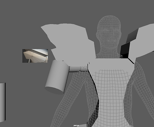
Here I have added detail to the shoulder pad and have started creating the arm of my mech. For the initial section I used cylinders and the extrude tool to make the desired shapes.
I made the arm's shape what I wanted by scaling it and rotating it accordingly as well as adjusting some of the vertices.
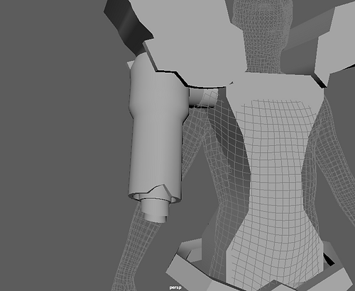
To make a shape more similar to what I was aiming for I had to use the extrude tool as well as the insert edge line tool to create vertices that I could adjust to manipulate the shape. I also created the elbow joint that would join the lower and upper sections of the arm by creating a cylinder, rotating and scaling it and then using the extrude tool.
After creating the joint I used a similar technique to what I did for the first section of the arm as it was similarly shaped.
I further adjusted the shape by using the edge line tool and using the vertices.
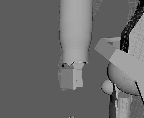
Afterwards I started the creation of the hand by creating a cylinder and modifying its subdivisions to create a hexagon that would serve as the wrist of the arm.
Following the wrist I used a cube which I scaled and rotated that would act as the palm of the hand that I will make for my mech.
I created what would be the upper part of the hand by creating a cube and adjusting the scale to what matched my design, and then rotated it so that I could position it properly. I also adjusted the palm of the hand by adjusting the vertices as this would change the shape to what I was looking for.
For the thumbs, I created some extensions that would be the joints between the thumb and the hand. To do this I created a cube and, after adjusting it, I used the bevel tool to create some more rounded edges that would be more accurate.
On the palm of the hands I used the extrude tool to create extensions on each side for the thumb and pinky finger.
On this joint I used the extrude tool to further extend it and end up creating the eventual thumb. I had to extrude multiple times as well as use the rotate tool to change the direction of it.
As soon as the basic shape of the thumb was made I use the insert edge line tool to create more vertices that would be manipulated to create the shape of the thumb that I was aiming for. Once I got this shape I mirrored it onto the other side to use it on the other extension that I had made before.
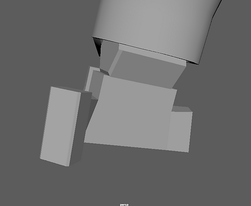
I created another cube and placed it to continue the finger. I used the vertices to adjust its shape and give it a more realistic look instead of only looking blocky.
After creating this cube I used it to create the rest of the shape of the finger by extruding it. I also used the bevel tool on the sides to make it have more rounded edges.
One the basic shape of the finger was done I used the insert edge line tool to insert some more edges into the shape and be able to manipulate it through the vertices to create the shape that I wanted to give the finger.
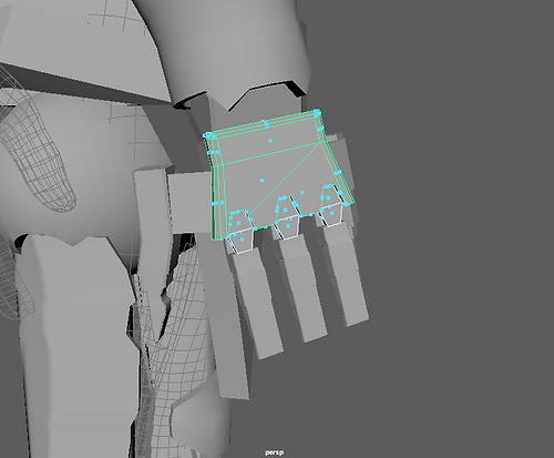
Once I was happy with the result I used shift+D to duplicate the finger into the positions that the other two fingers were placed in.
After I placed the fingers I then created a basic shape that would act as a joint and would imitate a knuckle. I placed this shape accordingly on top of each finger by duplicating it.
When I was done positioning them I used the boolean tool to create a space for this shape to make it look more accurate to what I was aiming for. To make it work I selected the hand first and then the three shapes and I then used the boolean > difference tool.
After this I then duplicated the original shape again into each of the spots that I did the boolean on to finish the hand.
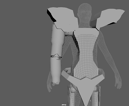
This screenshot shows the whole arm finished and mirrored onto the other side.
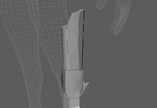
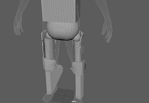
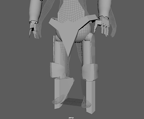
I decided to resize and readjust the legs at this point as I thought that they looked too thin compared to the rest of the mech's body.
In this screenshot I started modelling the chest of my mech. To do this I decided to use the extrusion method and extruded this face multiple times.
I also decided to improve on the shoulder pads by adding volume to it instead of leaving it as a mostly flat object as I decided that it would looked better this way than how it was before, as well as also matching my idea more accurately.
When I finished the upper area of the chest I worked on the lower area by using the same technique as for the first one. However, I did more extrusions to make a slightly more complex shape.
Once I finished with the chest area I decided to work on the waist guard. Based on what I wanted to achieve I extruded and manipulated the shape. However, due to the shape that I was aiming for it was slightly harder than the previous parts that I modelled.
I decided to go back to the shoulder guard and further improve on it by adding more volume to it and further manipulating it as I was not happy with my previous result.
Here I am showing an attachment that I decided to make. To create this shape I used the insert edge line tool as well as manipulating the vertices and subdivisions to create the shape of the attachment that I was aiming for.
I further expanded on it by creating an object that would resemble a blade by modifying the subdivisions and manipulating the vertices, edges and faces.
When I finished with the attachment I decided to create the back of the mech. To do this I started of by creating a cylinder on the top of the head and from there I adjusted the subdivisions and decided to extrude the ones at the back of the cylinder.
To expand on the base shape I decided to extrude some specific faces to make the back more similar to what I wanted it to look like for my mech.
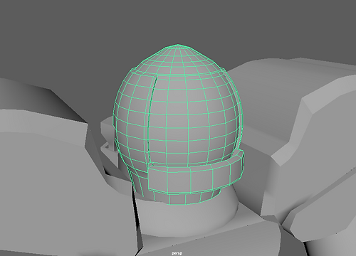
In this screenshot I have started working on the head of the mech. To create it I made a sphere and placed it on top of the cylinder I placed here before. I adjusted the lower vertices and extruded some faces in the lower area that would act as part of the helmet and armour.
After creating the base shape of the head and some parts I decided to extrude around the main front part that would be the visor, as extruding these areas would make it more evident.
To further develop the helmet I decided to extrude inwards too in this area to create a type of viewport.
This screenshot shows my finished mech fully rigged and with IK handles.

Rigged Mech
The goal of this project was to create a mech, rig it and then demonstrate how the rig works. The part that I enjoyed the most of this project was experimenting with rigging and then rigging my finished mech, as I thought it was fun and enjoyable to rig and try making animations with the models. Throughout this project I learned a lot about rigging techniques, as I learned how to auto rig as well as how to manually rig a variety of different models. I also learned how to animate in maya by using keyframes. I had some problems with the rigging as in some parts I had included too many bones and in others the bones were too straight, which were things I had to change and fix for the rigging to work properly. If I could start over I would use better time management to make my model more detailed and more accurate to what I was aiming for, as due to time constraints I had to keep some things more simple or different from what I wanted it to look like.
Evaluation